Wednesday, March 2, 2011

bandpass filter circuit

As the filter is a band pass filter there

As the filter is a band pass filter there

Circuit Diagram for a Tunable Band-Pass Filter

Circuit Diagram for a Tunable Band-Pass Filter

Circuit of operational amplifier active band pass filter
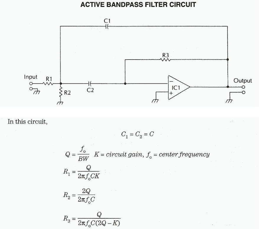
Circuit of operational amplifier active band pass filter

Band-pass. ↑ Top. Active Band-pass Filter Circuit
Band-pass. ↑ Top. Active Band-pass Filter Circuit

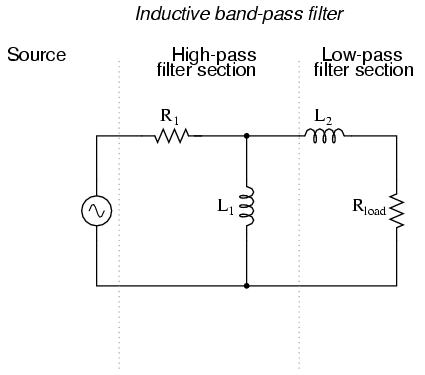
If we were to design a bandpass filter using inductors, it might look

If we were to design a bandpass filter using inductors, it might look

Bandpass filter Schematic (all four op-amps are used in the LM-348)

Bandpass filter Schematic (all four op-amps are used in the LM-348)

Bandpass and IF Filter Circuits · Bandpass filters

Bandpass and IF Filter Circuits · Bandpass filters

Filter Circuit for the Earthworm Seismic ». Responses are currently closed,

Filter Circuit for the Earthworm Seismic ». Responses are currently closed,

 other 7 MHz band-pass filter circuit or perhaps just design your own.

other 7 MHz band-pass filter circuit or perhaps just design your own.

This filter can be used in any circuit because of it's simplicity.

This filter can be used in any circuit because of it's simplicity.

How does a designer make a Twin T High Q Bandpass filter? Solution:

How does a designer make a Twin T High Q Bandpass filter? Solution:

Filter Circuit LC Filter Schematic. Fixed Capacitor: A capacitor with a

Filter Circuit LC Filter Schematic. Fixed Capacitor: A capacitor with a

Circuit of the operational amplifier active band pass filter

Circuit of the operational amplifier active band pass filter

Transmittance of a narrow band-pass filter.

Transmittance of a narrow band-pass filter.

Fliege Bandpass Filter transfer function's derivation

Fliege Bandpass Filter transfer function's derivation

Below are schematics of the respective Band and Low pass filter circuits

Below are schematics of the respective Band and Low pass filter circuits

Figure 1 - System schematic: Op-amp in a band pass filter. NODAL ANALYSIS
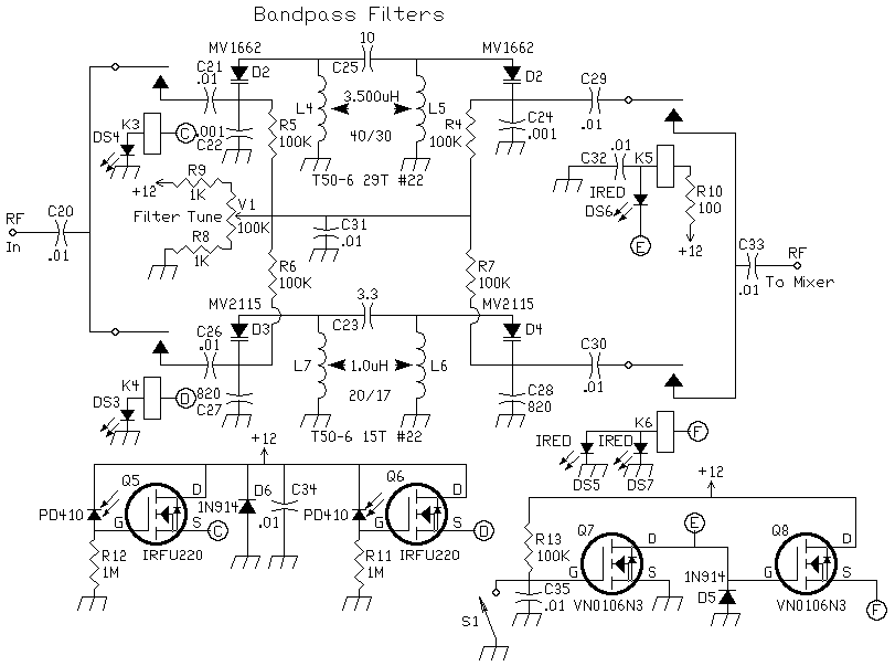
Figure 1 - System schematic: Op-amp in a band pass filter. NODAL ANALYSIS

Bandpass Filter Schematic
Bandpass Filter Schematic

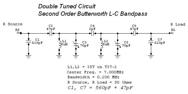
7 MHz Double Tuned Bandpass Filter. I designed this circuit using W7ZOI's

7 MHz Double Tuned Bandpass Filter. I designed this circuit using W7ZOI's

Figure Four, band pass filter used in experiement.

Figure Four, band pass filter used in experiement.